 In his 1936 report, The Parshall Flume, Dr. Parshall reported the results of a limited series of tests conducted on a 2-foot Parshall flume where the approach velocity was varied. His observation was that discharge through the flume was not significantly affected when approach velocities were almost 3 times the normal approach velocity of 1 ft/s [0.348 m/s].
Dr. Parshall did not, however, suggest that the Parshall flume was insensitive to approach velocities, merely that in his limited investigations that the flume studied did not experience significant changes in the discharge, as the variations was less than the experimental error. In deed, he went on to say that:
The Parshall measuring flume is primarily intended to operate under conditions where the (approach) velocities are moderate.
For applications where high velocities may be present, Dr. Parshall suggested that a narrow throat width flume should be used, whereby the depth of the upstream water would be increased and the approach velocity is decreased. Naturally this assumes that the smaller flume will handle the anticipated flow rates. Smaller, in this context, is a flume that is less than one half of the channel width guideline normally used (which is itself based upon the tradeoff of flume cost versus installation cost – with larger flumes requiring less work to transition flow into / out of the flume).
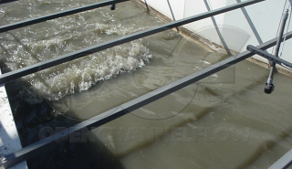
As part of their investigation on the field performance of over 220 Parshall flumes throughout Colorado, Ley et al took particular note of a 15-foot Parshall flume where approach velocities above a stage level of 3.00-feet [91.44 cm], on average, exceeded 4 ft/s [1.219 m/s]. A series of high flow measurements made over 10 years showed a consistent departure from the standard rating curve. Investigations shows that a high velocity “thread” of water in the center of the approach channel was present at the higher stage levels. On average, the higher velocity resulted in the flume passing 7.2% more flow than was otherwise indicated by the gauge level.
Ley et al's invesgations clearly show that Parshall flumes, while showing some insenstivity to approach velocities, are, nevertheless, subject to their effects.
Correcting for High Velocities
Where higher than desired velocities are experienced, or expected, steps must be taken to decrease the approach velocity for accurate flow measurements to be taken. A number of solutions have been developed to condition energetic influent flows.
These include: the use of a smaller throat width flume (as suggested by Dr. Parshall), drop manholes, energy absorbing manholes, flow straighteners, and tranquilizing racks.
Smaller Throat Widths
In natural channels, the use of a smaller throat width flume can be a viable option so long as the upstream channel banks will not be overtopped by the resulting increase in water level.
Nested / Dual Range Flumes
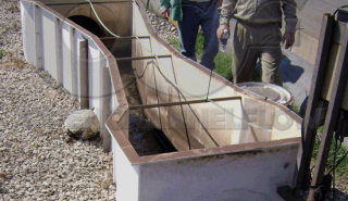
For sites where a flume already exists, a nested or dual-range flume may be installed to develop the desired upstream pooling. Depending upon the diameter of the manhole and the existing flume size, it may be possible to retrofit a nested Parshall flume in to an existing packaged metering manhole. Nesting Parshall flumes from 1-inch to 3-inches should present no problems – the 6-inch and 9-inch sizes could be questionable depending upon access in the manhole.
Energy Absorbing & Drop Manholes
For inline applications, Energy Absorbing and drop manholes may also be used. A drop manhole is simply a manhole place upstream of a flume’s location, which provides an abrupt change in elevation, slope, or line size. The change is intended to dampen energy of high velocity flows. Drop manholes should be located well upstream of the flume’s location to provide sufficient time for the flow to become tranquil – in general at least 30 times the maximum head upstream of the flume.
Similarly, excessive approach velocities caused by pumped flows or steep pip slopes can also be dissipated by fiberglass Energy Absorbing manholes. Unlike drop manholes which are intended to be place at sometimes considerable distance upstream of a flume’s location, Energy Absorbing manholes are to be inline, and just ahead of, a flume’s location (usually in a fiberglass packaged metering manhole).
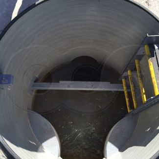
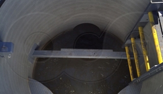
Energy Absorbing manholes feature a reinforced energy absorbing plate, which is set perpendicular to the direction of flow entering the manhole. The energy absorbing plate is larger (both in width and height) than the incoming line. High velocity water enters the manhole, hits the plate, and is directed around it. Once past the plate, the now dissipated, lower velocity flow is directed into the outlet pipe via smooth, radius wing walls. A distinct advantage of the Energy Absorbing is that, unlike drop manholes, it can be placed only a few feet upstream of a flume’s location.
Perforated Plates and Energy Absorbers
For locations where a change in a flume’s size is not possible or where adjustments to the upstream piping are not practical, two structures have been developed for insertion into the inlet of the flume itself. Both structures require that the flow stream be clean – there can be no solids (sanitary or other) in the flowstream as these will rapidly clog the structures.
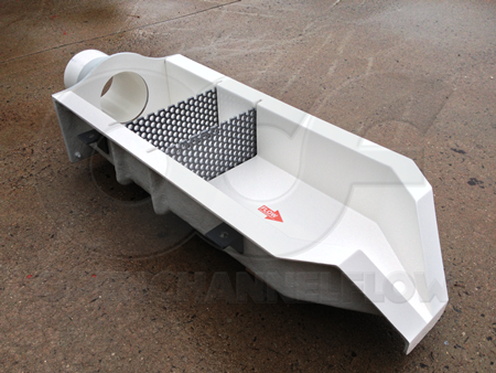
On small flume a series of Perforated Baffle Plates may be placed at the entrance of the flume. Used in a series of two or more, these perforated plates have a staggered hole pattern that helps to break up the flow pattern and dissipate energy.
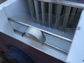
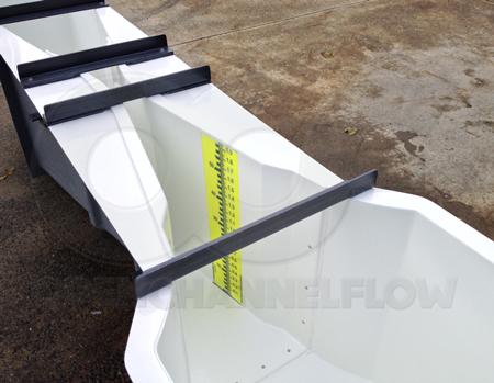
Energy Absorbers act in a manner similar to Energy Absorbing manholes. A plate is place in entrance of the flume (or, preferably, in the in upstream channel) against which the energetic flow impacts. As the lower velocity flow moves downstream it usually has some turbulence. Flow Straighteners are typically used downstream of Energy Absorbers to produce a good velocity profile as the flow approaches the point of measurement.
Image: The Knight-Risser Price for Western Environmental Journalism, Stanford University
Sources: Parshall, R., The Parshall Measuring Flume, Bulletin 423, Colorado Experiment Station, Colorado State College, March 1936, Ley, T. et al, Colorado Experience with Discharge Measurement at Parshall Flumes and Assessment of Parshall Flume Performance, Colorado Division of Water Resources, Skogerboe, V., Hyatt, L., England, J., Johnson, R., Design and Calibration of Submerged Open Channel Flow Measurement Structures: Part 2 - Parshall Flumes, Report No. WG31-3, Utah Water Research Laboratory, Utah State University, March 1967